
Before the first hard freeze
How to Drain a Backflow Preventer for Winter (PVB, RPZ, DC & AVB)
To drain a backflow preventer, first identify the exact manufacturer and model — not only whether it is a PVB, RPZ, double check or AVB — and follow that model's instructions: shut off and relieve the supply, open every drain path it names, and leave the valves in their specified winter positions. If anything is uncertain, arrange qualified backflow service.
A backflow assembly can retain water in its body, valves and risers. Recognizing a PVB, RPZ, double check or AVB is a first step, not a complete winterization procedure. Find the manufacturer, model and installation instructions; if any are uncertain, arrange qualified backflow service before opening parts or connecting air.
Working through it
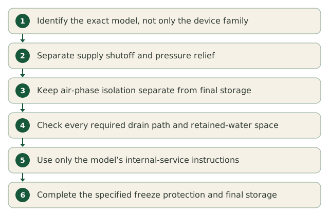
- Step 1
Identify the exact model, not only the device family
Use the representative drawings to recognize a possible device family, then read the actual model markings and obtain its freeze-protection instructions. The installation’s drain locations and air connection matter as much as the name. If you cannot verify them, use qualified backflow service.
- Step 2
Separate supply shutoff and pressure relief
Follow the model and installation instructions to close the upstream irrigation water supply and relieve pressure before opening drains or servicing the assembly. Do not work on pressurized fittings. The supply shutoff remains closed during winter; it is distinct from assembly valves that may later need a part-open storage position.
- Step 3
Keep air-phase isolation separate from final storage
A downstream air connection does not establish isolation. FEBCO 765 and Zurn 950/975 procedures, for example, close the assembly outlet isolation valve during downstream blowout and return it to the specified part-open position afterwards. These examples do not establish the procedure for another model. Use your model’s full sequence, not a final storage position during air flow.
Stop air and relieve pressure before changing the setup. Backflow manuals commonly specify about 45° for ball valves after the required drainage and air work. Follow the model’s positions for each valve and test cock; the main supply stays closed.
- Step 4
Check every required drain path and retained-water space
Test cocks alone do not prove complete drainage. FEBCO 765 and 850/860 instructions also address inlet/outlet drain paths; the 850/860 procedure includes model-specific internal handling. Relief-port flow on an RPZ does not prove every chamber is empty. Follow the exact manual or qualified service, including risers and connecting pipe.
- Step 5
Use only the model’s internal-service instructions
PVB bonnet or poppet removal is not universal, and merely loosening a bonnet does not prove drainage. Different DC/RP assemblies also have different cover and internal procedures. Do not disassemble from a generic device-family guide; use the manufacturer’s service instructions and any required testing before return to use.
- Step 6
Complete the specified freeze protection and final storage
Removal, draining, insulation or a heated enclosure must suit the actual model and installation. Union fittings alone are not instructions to remove a device. After any air work is stopped and pressure relieved, complete drainage and set the specified storage positions; keep the upstream water supply closed. Confirm any required reassembly and retesting with qualified backflow service.
Insulation alone does not establish that retained water is protected through a sustained freeze.
What “45°” looks like from above
Water can be trapped between a backflow ball valve’s ball and body with the valve fully open or fully closed. A half-open position can provide a drainage path where the manufacturer specifies it. These are representative schematics, not proof that a particular assembly is drained or permission to leave an air-isolation valve half open during blowout.
Open — normal service
Open flow through the bore does not prove the cavity between the ball and body is drained.
45° — specified storage position
Where the manual specifies 45°, use it for drainage and final storage after air is off and pressure relieved. Air-phase isolation is a different setting.
Closed — isolation, not proof of drainage
A closed valve may be required to isolate air or water during work. Afterwards, follow the model’s drainage and storage instructions; the water supply shutoff stays closed.
Device by device
PVB
Pressure Vacuum BreakerAbove groundA PVB is a single brass body on a riser about a foot above the highest sprinkler head, with a domed bonnet on top, two ball valves below it, and two small test cocks on the side. The most common device on residential irrigation in freeze country.
Drain it like this
- Identify the PVB manufacturer and model and obtain its freeze-protection instructions. If the model or drain arrangement is unknown, use a qualified backflow professional before opening parts or connecting air.
- Follow the PVB manual to shut off the water supply, relieve pressure and drain the assembly and both risers. The two test cocks alone may not drain every chamber.
- Bonnet or poppet removal is model-dependent. Do not loosen or remove internals on the strength of this drawing; follow the specified service and retest requirements.
- If the downstream piping is blown out, establish the manual’s air-phase isolation first. A downstream connection alone does not isolate the device.
- After air is shut off, pressure is relieved and drainage is complete, set the isolation valves and test cocks to the manual’s storage positions. Many specified ball valves use 45° at this final stage; the upstream water shutoff stays closed.
The mistake to avoid: Water retained between a ball and its valve body can freeze in either the fully open or fully closed position. Follow the exact model’s drainage and final storage directions; the outlet isolation setting during air work is a separate step.
RPZ
Reduced Pressure Zone assemblyAbove groundAn RPZ is the big one: two check valves in line with a relief valve hanging underneath that occasionally dumps water on the ground. Required where the system carries fertilizer injection or a higher hazard rating, and usually the most expensive device on the property.
Drain it like this
- Find the exact RPZ model and its freeze-protection procedure. Unknown models or drain paths need qualified backflow service before disassembly or air use.
- Follow the RPZ manual to shut off supply, relieve pressure and drain the body, risers and connecting pipe. The four test cocks and relief-port discharge do not establish that every internal chamber is empty.
- Internal check or relief-cover handling varies by model. Do not use a generic cover-loosening or removal procedure.
- For downstream blowout, isolate the assembly as the manual requires during air flow. Only after air is off and pressure relieved should final drainage and storage positions be completed. Ball valves commonly use about 45° for storage; follow the model for every valve and test cock, keeping the main supply closed.
- Follow the manufacturer’s freeze-protection and any service/retest requirements. Insulation alone does not establish that retained water is protected.
The mistake to avoid: Wrapping an RPZ assembly in insulation without draining it first. Insulation slows a freeze down; it does not prevent one, and a full assembly will still split in a sustained hard freeze.
DC
Double Check valve assemblyUsually below gradeA double check is two check valves in a single body with four test cocks and no relief valve underneath. Often installed below grade in a valve box, which is what makes it the least freeze-prone of the four.
Drain it like this
- Identify the exact double-check model and installation. If either is unknown, arrange qualified backflow service before opening parts or connecting air.
- Follow the double-check instructions to shut off supply, relieve pressure and drain the body, risers and connecting pipe. The four test cocks alone may leave water trapped inside.
- Use the model’s required drain paths and internal service procedure; another double-check model’s cover instructions are not interchangeable.
- Keep the manual’s air-phase isolation distinct from its final valve-storage positions. Complete final drainage and storage only after compressed air is stopped and pressure relieved. Ball valves commonly use about 45° for storage; follow the model for every valve and test cock, keeping the main supply closed.
- A double check in a below-grade box can still freeze, and the box does not prove the device has drained.
The mistake to avoid: Assuming a below-grade device is safe by definition. It is safer, not safe: a box under a cleared driveway with no snow cover freezes surprisingly deep.
AVB
Atmospheric Vacuum BreakerAbove groundAn AVB is the small, simple one — a single brass or plastic body downstream of each valve, with no test cocks and no isolation valves. Usually one per zone rather than one for the system.
Drain it like this
- Identify the AVB model and the zone’s approved winterization procedure; if unknown, use qualified help before applying air or opening components.
- A per-zone AVB has no test cocks or isolation valves in this representative arrangement. Colorado State Extension describes clearing it with its zone, while some general guides prohibit air through backflow devices. Verify the exact AVB and zone-valve instructions; do not apply a mainline assembly’s isolation sequence or assume every AVB permits air.
- Use the model-specific procedure for the valve, riser and downstream piping. Whether air is permitted depends on that equipment and installation.
The mistake to avoid: Looking for test cocks that do not exist and concluding the device has been dealt with. An AVB is only as drained as the zone it sits on.
When does your first freeze usually arrive?
The right sprinkler winterization method depends on your equipment, and the planning window depends on your location. Enter your ZIP for the NOAA freeze normals of the station we match to it — free, no signup required.
Free · no signup · NOAA 1991–2020 normals
Where this job usually trips people up
- Do I really have to leave the ball valves at 45°?
- Many specified backflow ball valves use 45° for drainage and final winter storage because water can be trapped between the ball and body when fully open or fully closed. Follow the actual model’s instructions. Temporary isolation during air work and the closed upstream water supply are separate requirements.
- Should I take the backflow preventer off for winter?
- Remove a backflow preventer for winter only if its manufacturer and installation instructions call for or permit that method. Confirm safe shutoff, pressure relief, storage, reassembly and any required retesting with qualified backflow service; unions alone do not establish a complete procedure.
- Can I blow air through the backflow preventer?
- Do not blow air through a backflow preventer unless the exact manufacturer procedure expressly permits it for your model and installation. Many procedures use an isolated downstream connection; downstream alone does not provide isolation. Watts 800M4 instructions describe a model-specific air purge, which is not permission to use it on another assembly. If unsure, use qualified backflow service.
- Mine is below ground in a box — is it safe?
- A backflow assembly in a below-grade box can still freeze, and being below grade does not establish that the assembly, risers or valve cavities have drained. Identify the model and installed drain paths and follow its freeze-protection procedure; do not apply another assembly’s instructions simply because both are double checks.
Get the reminder without scrolling back up
Enter your ZIP and we’ll set up the same reminder the ZIP tool higher on this page offers, timed to when it actually matters for your area.
Free · no signup · NOAA 1991–2020 normals
Check the instructions for your equipment
The equipment-manufacturer guides below explain the differences discussed here. Use the current instructions for your exact model, size and installation; an example for another device is not a procedure for yours. If you cannot verify them, use qualified service before connecting air or opening parts.
- FEBCO 765 winterization — IS-F-765-Winterization 2043 (2020), pages 1–2
- Zurn 950/950XL and 975/975XL freeze protection — Rev. C (July 2017)
- FEBCO 850/LF850 Small and 860/LF860 Small (½–2 in.) — 2344 (2023), pages 1–2
- Watts 800M4/LF800M4 — RP/IS-800M4 2409 (2024), Freeze Protection, page 2
- Rain Bird homeowner winterization guide — pressure and valve drainage, pages 3–6
- Hunter winterization guidance — component limits and air precautions
Where this guidance comes from
The university extension and public-agency publications listed here back specific statements on this page. Each publication says which statement it backs, so you can check the statement rather than take it on trust. Where a product label or your local extension office disagrees with anything here, follow the label or the extension office.
- Home Sprinkler Systems: Preparing Your Sprinkler System for Winter (Fact Sheet 4.719)
Colorado State University Extension
PVB and RP assemblies are not to be blown through with air, ball valves are left part-open for winter to avoid trapped water, and downstream isolation during blowout is a separate step.
- Home Sprinkler Systems: Backflow Prevention Devices
Colorado State University Extension
Backflow devices are damaged by freezing unless they are fully drained — the reason the page treats the device's freeze-protection procedure as its own job.
- Properly preparing irrigation systems for winter
University of Minnesota Turfgrass Science
Backflow ball valves and test cocks are commonly set at about 45° so trapped water can drain, and the exposed piping around the device is the most freeze-prone spot.
